A relay clicks on the bench, but the valve wired to its output stays closed. Did the valve receive power? A voltage measurement across the connected load will tell you more than the sound of the relay.
If you are sending a 24 V controller or remote I/O module out for assembly, define what “functionally tested” means before you place the pilot order. Ask the assembler to drive each specified input at its field terminal, read the channel in firmware, and measure each output under an agreed load. The test plan should say which boards get each check, what counts as a pass and which results you will receive.
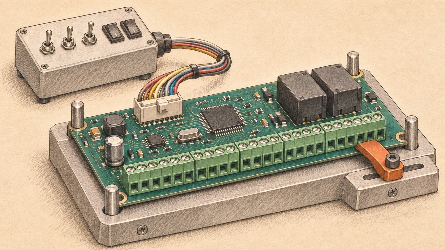
This fixture connects the board to an input simulator. Switching one channel at a time helps reveal swapped inputs.
Start with the sensor wiring diagram
Consider a packaging machine with two photoelectric sensors. One detects a carton at the infeed. The other confirms that the carton reached the sealing station. If the harness or firmware maps both signals to the wrong channels, the controller can boot normally and both indicator LEDs can light. A test that switches all inputs on together can miss the swap.
Give the assembler a connector drawing that shows the viewing direction, pin numbers, common terminal and software channel. Identify the sensor output type. A PNP sensor sources current to the input. An NPN sensor sinks current from it. The fixture must reproduce the wiring arrangement your board supports.
Write one test row that an operator can repeat
Suppose a board drawing assigns J3 pin 2 to DI2, and its test specification calls for a 24 V ON signal, a 0 V OFF signal and a 20 ms response limit. Start with all inputs OFF. Apply 24 V between J3-2 and its specified common. DI2 must read ON within 20 ms while DI1 and DI3 stay OFF. Return to 0 V and verify that DI2 clears within 20 ms. Repeat for each channel.
Those values illustrate a single board. If the product must recognize a sensor at the edges of its specified ON and OFF ranges, include those test points in the pilot plan. Select limits from the released board specification. For an example of how the input circuit affects thresholds and wiring, see the Texas Instruments ISO1212 datasheet.
What should a relay output do under load?
For a controller that operates a 24 V DC valve, identify the relay common, the contact used, the external supply and the valve coil. On a dry-contact output, the contacts switch a separate circuit. A fixture that only listens for a click leaves that circuit untested.
Specify the approved test load, connection and measurement point. For example, command the output ON and measure voltage across the fixture load. Command it OFF and verify the released state. If the field load is inductive, document the suppression arrangement. A resistor can be a repeatable production load once engineering has established which faults it detects. For one MY2 relay, OMRON lists 5 A at 24 VDC for a resistive load and 2 A for the specified inductive load with a 7 ms time constant. Check the data for the exact relay on your board. See OMRON’s explanation of relay load ratings.
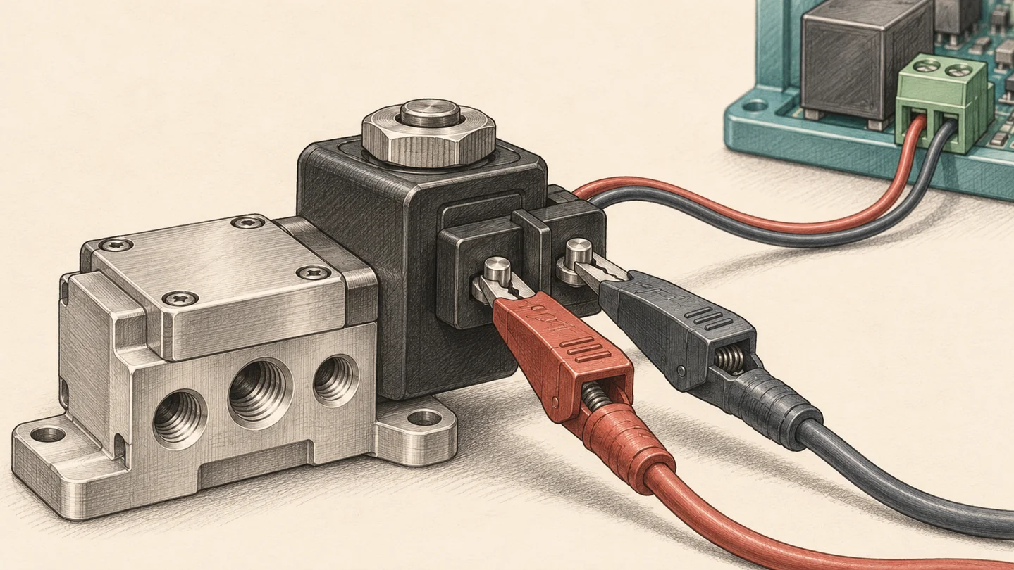
The test clips measure voltage across the valve coil while it is connected. Record the readings with the relay commanded both ON and OFF.
A functional test checklist for a 24 V I/O board
Use the rows that match the product. Add the pin numbers, limits with units, test frequency and record required for each row before sending the plan for quotation.
| Function | What the fixture does | What counts as a pass |
|---|---|---|
| Power and startup | Apply the specified supply and start the released firmware. | Current and startup time fall within the approved windows. Outputs reach the defined startup state. |
| Digital inputs | Drive one channel at a time through its field connector. | The intended register bit changes and clears on time. Other monitored bits retain their expected states. |
| Relay outputs | Command one output at a time with the approved load attached. | The intended load sees the specified ON and OFF values. Adjacent outputs stay in the required state. |
| Communications, if fitted | For a Modbus RTU design, send a defined request via the external RS-485 connector. | The intended device replies with the expected register value within the specified timeout. |
Automated optical inspection (AOI) can flag visible placement and soldering faults. A powered functional test exercises the input, firmware and output paths covered by its procedure. VOSNOR describes these methods on its PCBA testing and inspection page.
Which checks belong in the pilot build?
Use the pilot to prove the fixture can detect a bad board. Alongside a known-good sample, use an approved fault simulation, such as opening one input wire in the test harness. If the station still reports PASS, correct the test before releasing the batch. Save the approved fixture drawing, test script and firmware revision together.
A pilot can also answer a question that would slow down every unit on the line. For the packaging machine, engineering might validate switching with the actual valve and harness at the specified supply limits. The repeat order can then use an agreed fixture load at nominal supply for every board. Record which conditions were validated on pilot samples and which are checked on each shipped unit.
How to compare two PCB assembly quotes
Ask each supplier to separate one-time fixture and software costs from per-board programming and test labor. Then check which channels the quote covers, what load the fixture uses, how many boards will be tested and what results you receive. Two quotes can both say “functional test included” while one covers startup and the other exercises every I/O channel.
For example, a hypothetical $600 reusable fixture adds $6 per board on a 100-board order. Over 1,000 boards of the same revision, it adds $0.60 per board before test labor or maintenance. Confirm who owns the fixture, where it will be stored, and who approves changes when the connector or firmware is revised.
What to send with your request for quotation
Send the bill of materials with approved manufacturer part numbers, PCB fabrication and placement files, assembly drawing, pilot and repeat quantities, and target dates. For industrial control board testing, include the pin map, firmware build, programming instructions, test limits and a load description. Flag any missing item and name the person who can approve it.
Example wording for an RFQ. “Please quote the pilot and repeat lots separately. Include programming and a functional test on every unit. Exercise each digital input and relay output listed in our pin map using the loads and limits in the attached procedure. Show one-time fixture costs and per-board test costs separately, and provide a sample results file for approval.”
Ask for a sample test record before placing the repeat order. A useful record links the board or lot ID to the firmware and test revision, names the channel that failed, and keeps the original result alongside any approved repair and retest. Agree whether the shipment requires individual readings or a lot summary.
If you are sourcing a controller or remote I/O board, share the pin map, expected quantities and available test requirements with VOSNOR. We can review assembly, programming and test coverage against your design. Request an industrial control PCB assembly review.