Motor Control Board Design for a Handheld Eye Trainer
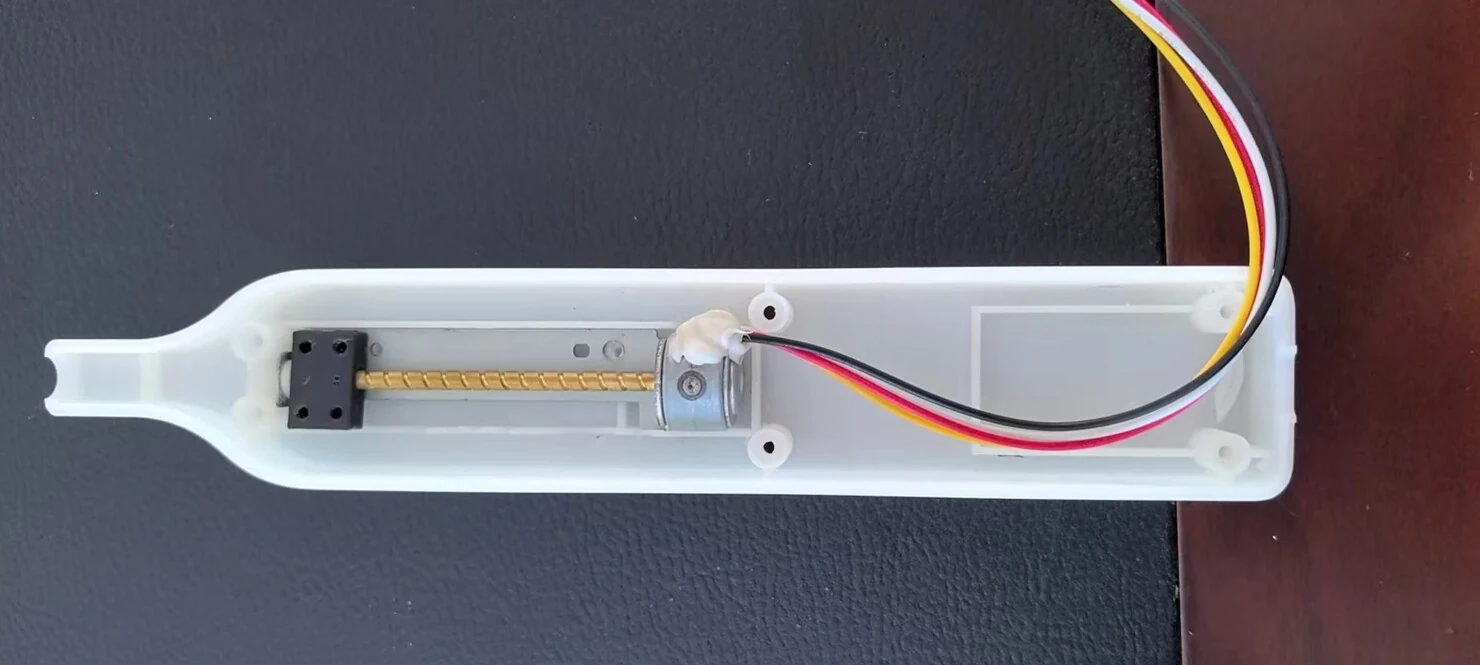
The customer specified a 45 mm stroke in no more than two seconds. The design review focused on how the control board could detect when the slider reached either end, and where the two Hall switches would fit inside the handle.
Travel time and end-of-travel detection
The customer requested two versions. The basic model had no display: one press to raise the slider and a second to lower it. The display version added a choice of manual operation or 5-, 10- and 15-second automatic cycles. Each cycle allowed two seconds up and two seconds down. Only the pause at the top varied.
The customer initially proposed stopping the motor on a timer. The engineer pointed out that travel time depends on motor speed. After comparing a slotted optical switch with a magnet and Hall switch, the customer chose Hall switches for both ends of the stroke.
| Cycle setting | Rise | Hold at top | Descend |
|---|---|---|---|
| 5 s | 2 s | 1 s | 2 s |
| 10 s | 2 s | 6 s | 2 s |
| 15 s | 2 s | 11 s | 2 s |
Hall switch placement and sensing gap
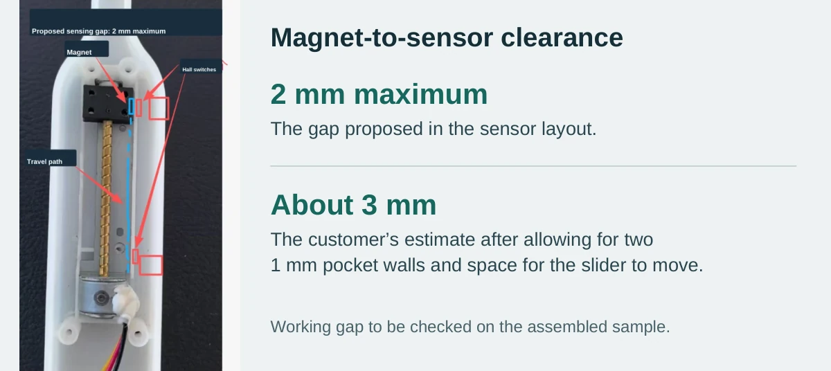
In the proposed layout, one magnet travels with the slider. A Hall switch at the top of the housing detects the magnet at the upper limit. A second switch detects it at the lower limit.
The layout drawing specifies a maximum gap of 2 mm between the magnet and the switch. The customer estimated about 3 mm: the magnet pocket and the switch pocket each had a 1 mm wall, and the slider also needed room to move.
To reduce the gap, the engineer suggested embedding the magnet in the plastic slider and fitting the switch directly against the housing rib. The actual gap and both trigger positions still need to be checked on an assembled sample.
Fitting the main control board into the handle
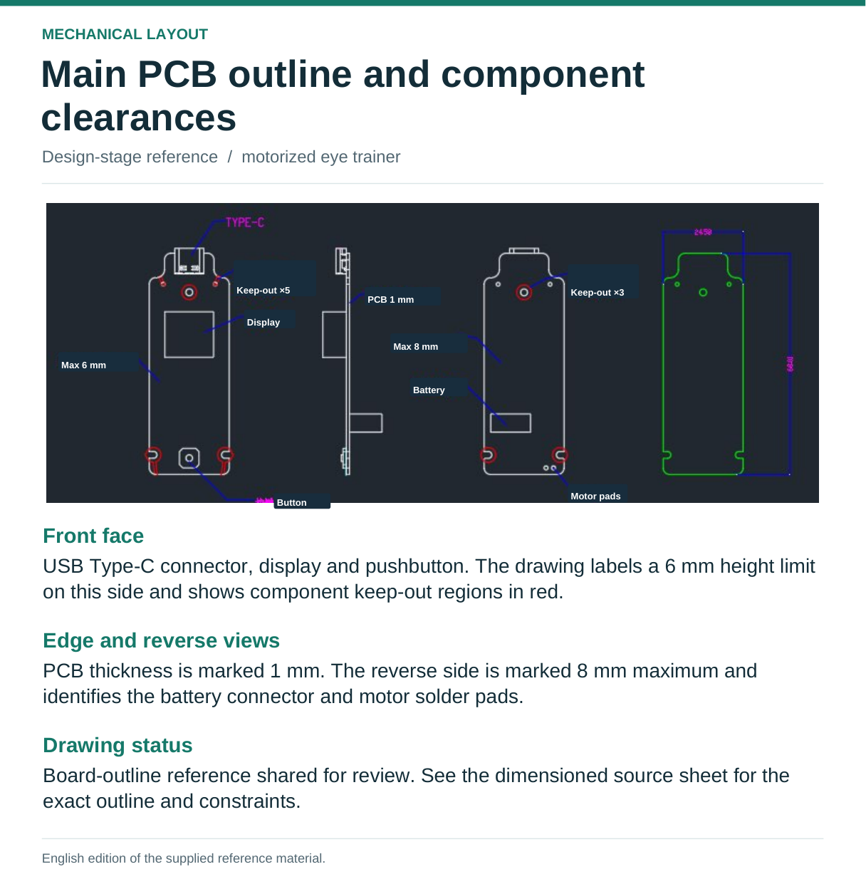
The display, pushbutton and USB-C connector had to line up with the housing. The main PCB drawing set a board thickness of 1 mm and component height limits of 6 mm on the display side and 8 mm on the reverse. The red outlines mark areas to keep clear of components.
Checking the display and pushbutton positions
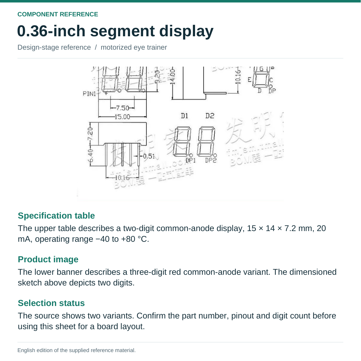
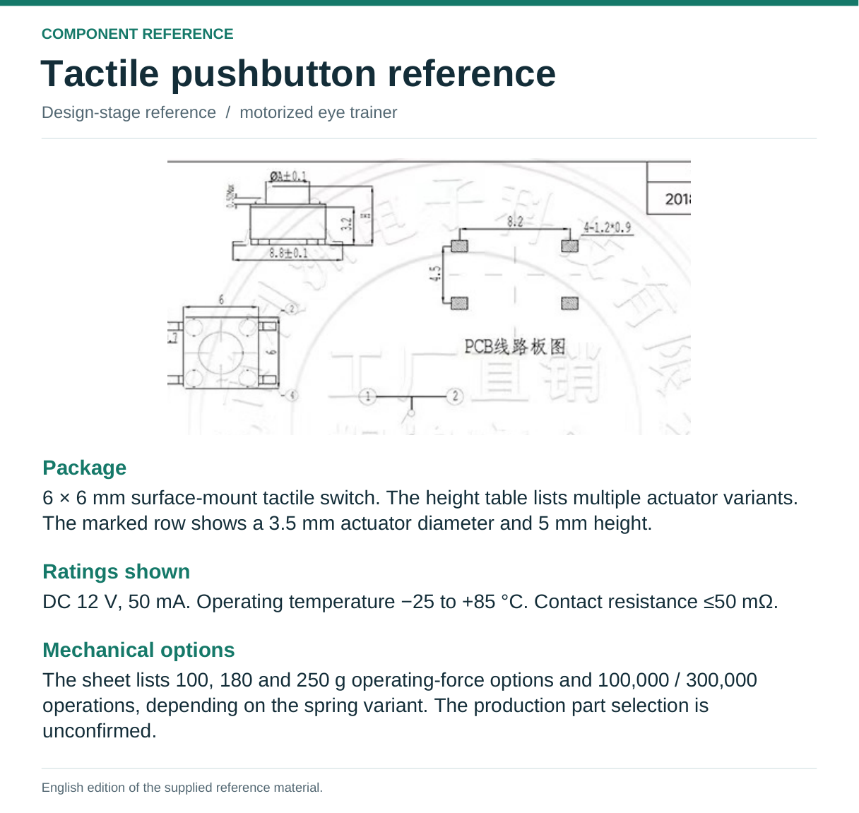
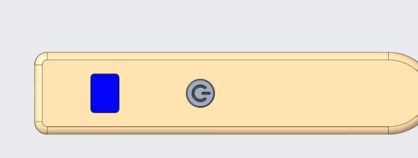
The early housing drawing shows a display window and one power button. A separate proposal added plus and minus buttons for setting the clock and accessing training records. The display reference shows both two- and three-digit parts, so it does not establish a final footprint.
Hall sensor board dimensions and prototype checks
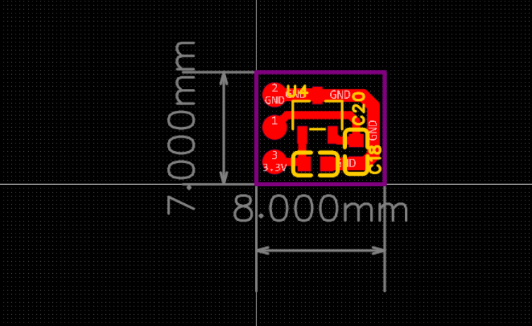
The Hall sensor board drawing shows an 8 × 7 mm outline. This is the small board at the end of the stroke. The main control board sits in the lower half of the handle and has a separate outline drawing.
The customer chose the display version for the first development round. Three checks remain for the assembled sample: measure the magnet-to-switch gap, record where each switch triggers, and time the full 45 mm stroke in each direction.