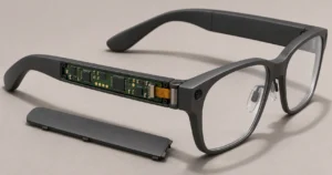
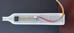
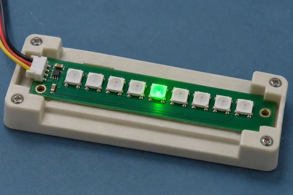
A sample board can light up and still fail a customer’s inspection. Suppose the first eight pixels follow the startup pattern and the rest stay dark. Is the ninth LED defective, is power missing at that point, or did the data stop at pixel eight? A photo of the lit board cannot answer that question.
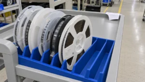
When you request a quote for a custom addressable LED board, agree on how the assembler will handle open reels, verify the reflow profile and test every pixel position you need to control. Those details make two assembly quotes much easier to compare.
Why WS2812B LEDs flicker or stop partway along a board
Each WS2812B pixel reads its own color data and passes the remaining data to the next pixel. A break at one position can leave several healthy LEDs dark. The failure pattern gives an engineer a place to start.
| What you see | Where to look first |
|---|---|
| The chain goes dark after one pixel | With a pattern that addresses the entire board, check power at the first dark pixel. Trace data from the output of the last working pixel to the input of the next. Inspect the joints between them. |
| Pixels flicker as brightness rises | Reproduce the fault at the intended brightness. Measure supply voltage on the board under load, then check the shared ground and the data level at the first pixel. |
| Red and green are consistently swapped | Send red, green and blue separately. Compare the controller’s color order with the LED specification before replacing parts. |
Moisture control when a reel is opened
Moisture absorbed by an LED package can cause damage when the part is heated during reflow. The moisture sensitivity level (MSL) and the permitted time out of dry storage depend on the selected part and its handling instructions.
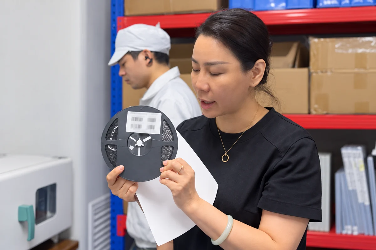
One question is especially revealing on a small pilot run: “If only half the reel is used today, how will the next shift know how much exposure time remains?” Ask how the reel is identified, when the exposure clock starts and how the remainder is stored. If the limit was exceeded or the history is unknown, set the reel aside. Before baking, check the manufacturer’s drying instructions and the temperature rating of the reel or tray.
How to verify the WS2812B reflow soldering profile
An oven recipe shows the zone settings and conveyor speed. A measured profile shows the temperatures the assembled board actually reached. Ask where the thermocouples were attached on a representative board and which LED and solder-paste limits the engineer used to evaluate the trace.
For example, if the LED specification defines a peak temperature at the package surface, check that the profile includes a measurement there. The solder paste has its own process window at the joint. If a double-sided board goes through the oven twice, include the second pass in the review.
How to test each pixel after assembly
For a status panel, a board can show the right colors and still light the wrong indicator. Give the assembler a drawing that maps each pixel position to its function. For a decorative board, supply the approved startup or animation sequence and the brightness at which it will run.
A practical test starts with all pixels off. Move one lit pixel from the first position to the last, then repeat in red, green and blue. Confirm that the intended position lights each time, the other positions stay dark and the last pixel receives its command. Finish with the intended operating pattern at the agreed supply voltage and brightness.
Example acceptance wording for a request for quotation (RFQ)
“Test every assembled board. Step a single pixel through every position in red, green and blue. Pass only if the commanded position and color match the drawing, all other pixels remain off at each step, and the sequence completes at the last pixel.”
Specify coverage when comparing prices. A test on every board and a check on a sample of boards represent different scopes of work. If a board fails, recording the first affected pixel and the board revision helps engineering reproduce the fault. Specify any color-matching limits or burn-in duration separately.
What to send for an LED PCB assembly quote
Send VOSNOR your bill of materials (BOM), Gerber and drill files, pick-and-place file, assembly drawing, and prototype or production quantities. Include a pixel map or a short video of the expected behavior. If the LED selection is still open, flag it for review and state who can approve a substitute.
For turnkey LED PCB assembly, tell us which components you would like us to source and what the finished board must do at handover. We can then review the sourcing, assembly and test scope with your team.