A customer designing a handheld eye trainer wanted a motor-driven slider to travel 45 mm in two seconds or less. The first idea was simple: power the motor for two seconds, then stop. But if the motor turned more slowly than expected, the timer would expire with the slider still short of its destination. How could the control board tell where it actually stopped?
The customer chose two Hall effect limit switches, one for each end of the stroke. The harder question was where to put them. Inside the handle, even the wall of a plastic pocket counted toward the distance between a switch and its magnet.
What the timer controls and what the switch detects
Consider the 10-second cycle the customer requested. The slider had two seconds to rise, six seconds to pause at the top and two seconds to return. The 5- and 15-second cycles changed only the pause, to one and eleven seconds respectively. In all three modes, the controller could count the pause precisely. To know when the slider had arrived at the top, it needed a signal from the mechanism.
The team considered a slotted optical switch and a magnet-operated Hall switch. In the selected layout, a single magnet moves with the slider. The upper switch signals when the magnet reaches the top of the stroke. On the return trip, the same magnet passes the lower switch. Those two signals give the controller a way to identify each endpoint. Position between the endpoints remains unknown.
Where the extra millimetre came from
The engineer’s drawing called for a magnet-to-switch gap of 2 mm or less. The customer’s enclosure estimate was about 3 mm. Both figures made sense once the two parts were drawn together. The magnet sat behind a 1 mm pocket wall, the switch sat behind another 1 mm wall, and the slider needed clearance to move. The two walls alone used up the proposed gap.
The engineer suggested embedding the magnet in the plastic slider and placing the switch directly against a housing rib. That gave the enclosure designer a specific dimension to check on the first sample. The 2 mm figure was the target for this layout. A different magnet or switch would need its own gap assessment.
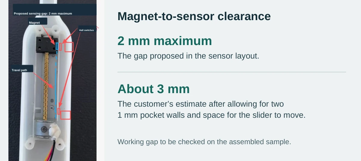
The drawing compares the engineer’s proposed maximum with the customer’s enclosure estimate. View the annotated original.
What to record on the first assembled sample
- Gap at each end. Measure from the installed magnet to each switch with the sensor boards seated in the housing. Record upper and lower values separately so a difference between the two mounting positions is visible.
- Trigger position. Move the slider in each direction and mark where the corresponding switch changes state. Compare that point with the intended endpoint. This also helps distinguish a switch that triggers too early from a slider that stops short.
- Travel time. Time the full 45 mm stroke upward and downward under the intended load. Compare each reading with the customer’s two-second limit and record the dwell time separately.
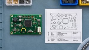
These three measurements are still pending for the eye trainer. The motor control board case study includes the enclosure drawing and the 8 × 7 mm sensor board layout used in the review.
If you are preparing a similar mechanism for prototype PCB assembly, send the motor specification, the target stroke and a cross-section through the magnet and switch pockets. Those details give the mechanical and electronics teams a common starting point for the first functional test.
Planning a similar mechanism? Send your motor specification and enclosure drawing for a sensor placement review.