A buyer has found a 4.7 µH power inductor that fits under the lid of a 5 A buck converter. It saves 2 mm of height and has a slightly higher saturation-current rating than the original. Can purchasing release the production order?
Order pilot quantities first. In this example, the shorter inductor reaches the manufacturer’s 20 °C temperature-rise benchmark at 4.3 A. The proposed rail carries about 5 A RMS. The part could still work on the finished board, but the buyer needs an enclosed-board temperature result before committing to a production reel.
The two Coilcraft parts below are real. The enclosure, converter and load are a worked example. The waveform and loss figures are calculated.
What should purchasing check before ordering samples?
Start with the exact manufacturer part numbers and the assembly drawing. Here, the drawing allows 4.0 mm above the PCB. The shorter part leaves 0.9 mm against that limit. The taller one exceeds it by 1.1 mm. Confirm the land pattern and the enclosure tolerance stack before treating that 0.9 mm as usable clearance.
| Manufacturer specification | Shorter part · XAL5030-472MEC | Taller part · XAL5050-472MEC |
|---|---|---|
| Maximum height | 3.1 mm | 5.1 mm |
| Nominal inductance at zero DC bias | 4.7 µH ±20% | 4.7 µH ±20% |
| Saturation current at 25 °C | 6.7 A | 6.6 A |
| Current for a 20 °C rise from 25 °C ambient | 4.3 A | 6.1 A |
| Typical winding resistance at 25 °C | 36 mΩ | 22 mΩ |
The manufacturer publishes the electrical test conditions, inductance curves and mechanical drawings together. Coilcraft XAL50xx specifications and package drawings
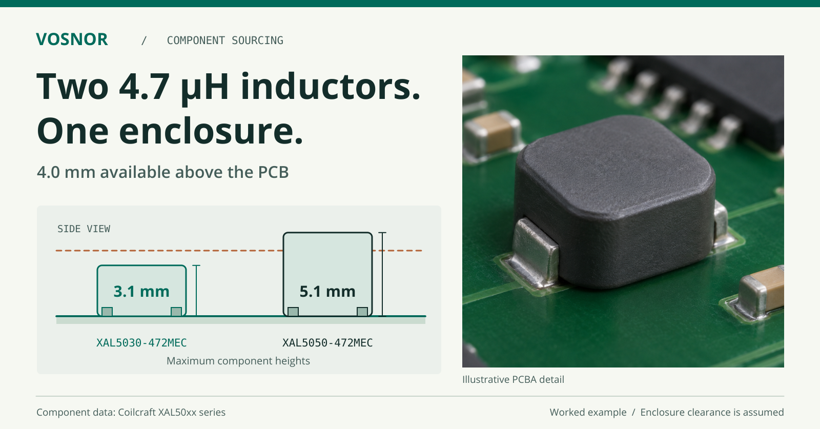
The shorter package clears the assumed lid height by 0.9 mm before assembly tolerances.
If the line is waiting for material, ask the supplier to quote samples separately from the production reel and state how long the stock can be held. Record the proposed part against the board revision and pilot quantity. That gives the buyer permission to keep the build moving while engineering evaluates the part. VOSNOR’s component substitution approval form
What does inductor saturation current tell you about a 5 A rail?
For these two parts, Coilcraft defines saturation current (Isat) as the DC current that reduces inductance by a typical 30% at 25 °C. By the time the shorter part reaches its published 6.7 A rating, it has already lost a substantial fraction of its zero-bias inductance. That rating alone cannot tell an engineer how hot it will run at a continuous 5 A.
The thermal rating answers the question that matters to this buyer. Under the manufacturer’s test conditions, 4.3 A produces a 20 °C rise in the shorter part. On the actual assembly, board copper, airflow and nearby heat sources affect the result. Before the pilot build, agree on the maximum component temperature or allowable temperature rise for the finished product. That gives the engineer a pass/fail criterion and the buyer a clear release condition.
How much inductor ripple current flows at full load?
Consider a 12 V input, 5 V output and 500 kHz switching frequency. Using the nominal 4.7 µH and assuming ideal steady-state continuous conduction, the duty cycle is 5/12. The inductor sees about 7 V for 0.83 µs during each on-time.
Using ΔI = V × Δt / L gives 1.24 A peak-to-peak ripple. At a 5 A average load, the current swings from 4.38 A to 5.62 A, with an RMS value of approximately 5.01 A. Texas Instruments’ buck converter power-stage calculations
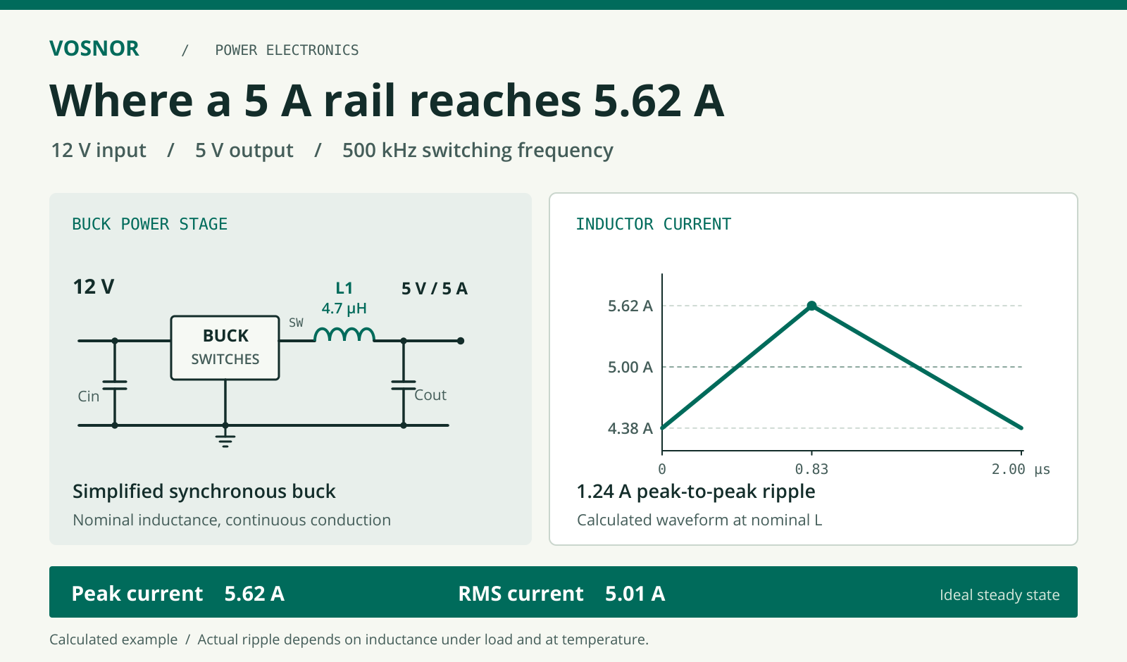
With nominal inductance at 500 kHz, the calculated ripple is 1.24 A peak to peak and the RMS current is 5.01 A.
For the release calculation, use the product’s input-voltage range, minimum switching frequency, inductance tolerance and the supplier’s inductance-versus-current curve at the relevant temperature. Lower effective inductance increases ripple. On a peak-current-limited controller, check the measured peak against the controller’s guaranteed minimum current-limit threshold, including the margin your design requires.
How much winding loss does inductor DCR add?
At 5 A, the typical DC winding resistance (DCR) gives a useful first estimate. The shorter part dissipates about 0.90 W from the DC component of the current (5² × 0.036 Ω). The taller part dissipates about 0.55 W (5² × 0.022 Ω). Saving 2 mm of height costs approximately 0.35 W of additional winding loss at this operating point, using resistance at 25 °C. Core loss, AC winding loss and the increase in resistance as the winding heats also affect the final temperature.
A bench supply can still read 5.00 V while the winding is heating. For a product that ships in a closed housing, measure stabilized component temperature with the lid fitted, at the specified ambient temperature and with the airflow the customer’s unit will actually have.
What evidence releases the production order?
| Check | Evidence to attach to the approval |
|---|---|
| 机械配合 | Verify the soldered component height, production PCB, lid and tolerance stack against the assembly drawing. |
| Electrical performance | At full load and maximum specified input voltage, capture inductor current and output ripple. Record the probe setup and compare the results with the design limits. Include startup or a load step if either produces the highest current in this product. |
| Temperature | Run the assembled product at its hottest specified ambient and the operating condition that produces the most heat. Record ambient temperature, stabilized inductor temperature and the agreed limit. |
| Purchasing release | Attach the results to the exact part number and board revision. Have the design owner identify the approved quantity or production scope before purchasing commits the balance. |
A practical note for the purchase order reads:
XAL5030-472MEC approved for pilot units on the stated board revision. Production release requires signed results for enclosure clearance, current waveform, output ripple and stabilized inductor temperature.
If a result exceeds its limit, keep the pilot units traceable and reopen the component or enclosure choice before the next build.
Quoting a pilot build with an alternate inductor? Send VOSNOR both part numbers, the BOM revision, enclosure-height limit, load profile, thermal limit and required build date. Those details let us scope the samples and agree on the functional tests with your team. Review VOSNOR’s PCBA testing capabilities · Request a BOM and pilot-build review.